1、 Overview of Magnetic Integration Technology
Magnetic integration refers to the use of a single magnetic component to achieve the functionality of multiple magnetic components. From the perspective of magnetic flux, magnetic integration can be divided into two categories: decoupling design and coupling design.
Decoupling design: In this design, there is no magnetic flux coupling between multiple magnetic components except for sharing a common magnetic column. Therefore, its magnetic circuit model is independent, and the design and analysis process is relatively simple.
Coupling design: In this design, there is magnetic flux coupling between two independent magnetic components, which means that during operation, the magnetic components will affect each other. Therefore, its design and analysis process is more complex, but the degree of magnetic integration is higher.
From the types of integrated magnetic components, magnetic integration can be divided into the following three categories:
1. Inductance and inductance integration: One of the most typical applications is the interleaved parallel Boost inductance magnetic integration.
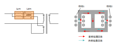
Another approach is the integration of differential and common modes. When designing high-power magnetic components, parallel winding scheme is usually adopted. However, if the structure is asymmetric, it can lead to uneven current between parallel windings. To suppress this uneven current, it is necessary to add a differential mode inductor.
The specific plan is to add a middle column on the basis of the double column resonant inductor, which serves as a circuit for differential mode magnetic flux. Due to the small difference modulus component itself, the cross-sectional area of the center column is relatively small. Through this method, the magnetic integration of differential mode inductance and common mode inductance has been achieved.
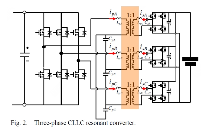
2. Transformer and Transformer Integration: Matrix transformers are popular in academia. For example, the topology structure of primary side series connection and secondary side parallel connection can be achieved through a four column planar transformer. This magnetic integration method is suitable for high turn ratio scenarios, such as server power supplies. However, in high-power scenarios such as charging stations, three-phase topology is more commonly used.
Due to the zero sum of the magnetic flux of the three magnetic components in the three-phase topology, the common column can cancel out, thereby achieving a three-phase three column transformer.
Three port magnetic integrated isolation transformer
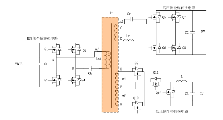
For car power supplies, at least two isolated DC-DC circuits are usually required, one for OBC and the other for DC-DC. By utilizing a three winding transformer for AC coupling, any energy flow between the three ports can be achieved, greatly improving system integration.
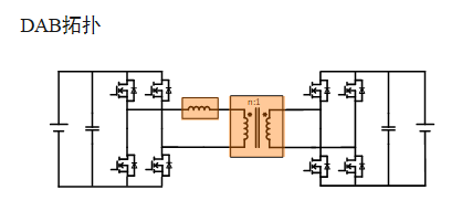
3. Integration of inductance and transformer: This integration method is suitable for basic topologies, especially LLC and DAB topologies. These two topologies can achieve soft switching with high efficiency, making them widely used in medium to high power scenarios. Although LLC topology also has bidirectional CLLC topology, considering cost-effectiveness, it is currently mainly used in scenarios where unidirectional energy flow occurs, such as unidirectional OBC and charging piles.
Multiphase integrated transformer
DAB topology is mainly used in scenarios where energy flows in both directions, such as bidirectional OBC and household energy storage.
The common feature of these two topologies is the inductance connected in series with the transformer (labeled as LR in the figure).
Generally speaking, the resonant inductance of LLC topology is smaller to achieve a wider range; The inductance of DAB topology is relatively large to improve control accuracy. From the perspective of magnetic integration, achieving large leakage inductance in DAB is more difficult.
2、 Magnetic Integration Design Scheme - Conjugate Magnetic Integration
The history of magnetic integration technology can be traced back to nearly 100 years ago. In recent years, with the rapid development of technology, some mainstream magnetic integration solutions have been formed.
However, in the actual implementation process, this technology has a high technical threshold. If the design is reasonable, the magnetic integration scheme can reduce the number of magnetic components, improve the efficiency of the system under all operating conditions, and reduce the cost and volume of magnetic components. But if the design is not reasonable, it may lead to the magnetic integrated transformer becoming very complex in structure and process, thereby increasing labor costs, and even decreasing efficiency in individual or full operating conditions.
The most common problem is the local temperature rise of transformers after magnetic integration, which is currently the most common issue we encounter. Therefore, for magnetic integration technology, the design phase is crucial.
Regarding this, Cai Guoqing shared two design methods for magnetic integration; One is conjugate magnetic integration, and the other is leakage induced magnetic integration. Due to space limitations, the article on leakage induction magnetic integration will be published in the next issue. This article will focus on introducing the principle and design scheme of conjugate magnetic integration.
01. Analysis of Conjugate Magnetic Integration Principle
In theory, any magnetic component can achieve decoupling magnetic integration through a common column. However, if only physical integration is carried out, the advantages of magnetic integration are not fully utilized.
Because the magnetic flux of the two integrated magnetic components is a vector, if these two components are of the same frequency on the common column and have a fixed phase difference, partial cancellation can be achieved using the principle of magnetic flux superposition.
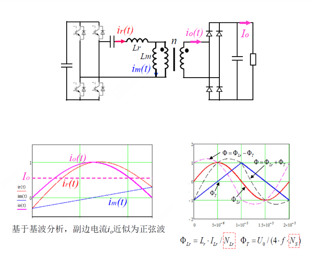
Taking the LLC topology in the following figure as an example, in fundamental wave analysis, it can be considered that the secondary current (IO) is approximately a sine wave. The excitation current of the transformer is stimulated by the secondary voltage, so its excitation current can be regarded as a triangular wave with a lag of 90 degrees.
The resonant current of the primary side is equal to the secondary side current converted to the primary side, plus the excitation current. Due to the relatively small excitation current, the primary current still tends to be a sine wave as a whole. However, due to the 90 degree phase difference between the excitation current and the secondary current, when the two 90 degree phase difference vectors are superimposed, there will be a phase difference of less than 90 degrees between the primary current vector and the secondary current vector.
For transformers, their magnetic flux is proportional to the excitation current, while the magnetic flux of resonant inductors is proportional to the resonant current. Therefore, the magnetic flux of a transformer is a triangular wave, while the magnetic flux of an inductor is an approximate sine wave that leads less than 90 degrees. When they are superimposed in the forward or reverse direction, the amplitude of the superimposed magnetic flux is smaller than the sum of the transformer and inductor magnetic flux amplitudes. This can reduce the amplitude of the magnetic flux in the conjugate part, thereby achieving magnetic integration, which is its basic principle.
02. Design Methods and Optimization
After understanding the principle, we will find it easier to design.
One option is to design discrete magnetic components first, and then perform conjugate magnetic integration. Due to the independence of transformers and inductors, their respective loss reduction measures are still applicable.
For example, transformers can adopt a sandwich structure, and inductors can adopt segmented air gaps. However, it should be noted that when designing separated magnetic components, in order to achieve conjugation, transformers and inductors need to use magnetic cores of the same specifications.
However, in general, the magnetic core of a transformer is relatively large, resulting in a larger window area and height, while the window height of an inductor is usually smaller. Therefore, the process of using segmented air gaps in inductance loss reduction will be relatively complex.
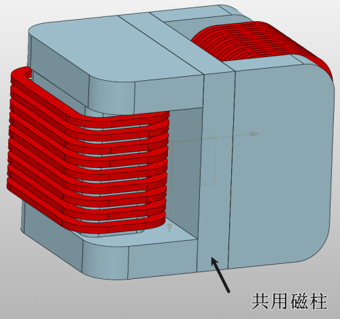
The second part is the common magnetic yoke, where the transformer flux and inductor flux can be superimposed in the same direction (DAB) or opposite direction (LLC).
For DAB topology, it is analyzed that the angle between the inductance flux and the transformer flux is slightly greater than 90 degrees, so it is usually recommended to use the same direction setting scheme.
For LLC topology, if the angle between the inductance flux and the transformer flux is less than 90 degrees, it is recommended to use a reverse setting scheme. Specific settings can be achieved by adjusting the winding direction of transformers and inductors.
The following figure shows the magnetic flux superposition and cancellation waveforms of LLC topology, and it can be seen that the magnetic flux amplitude is lower when set in reverse.
Thirdly, standard magnetic cores are generally used for magnetic cores, and the magnetic flux of the common yoke is superimposed, resulting in a higher magnetic flux density.
In practical production, since the inductor and transformer are connected in series, theoretically the inductor can be wound with the same wire as the transformer winding on the same side. This can reduce solder joints, lower production costs, and currently the process can achieve automated production.
In magnetic integration design, due to the superposition of magnetic flux on the common magnetic column, although its amplitude is less than the sum of the amplitudes of two magnetic fluxes, it is still greater than the amplitude of any one magnetic flux. In practical design, we do not actively increase the area of the common magnetic column, so the magnetic flux density of the common magnetic column is usually higher.
The fourth is to avoid saturation of the common magnetic yoke and excessive magnetic loss.
When conducting temperature rise analysis, if the cross-section of the common yoke is the same as that of the upper and lower yokes, the temperature rise of the common magnetic column is often slightly higher. To avoid saturation of the common magnetic yoke and excessive magnetic loss, special attention needs to be paid to the magnetic flux on the common magnetic column. The magnetic flux of the common magnetic column is the superposition of transformer magnetic flux and inductor magnetic flux.
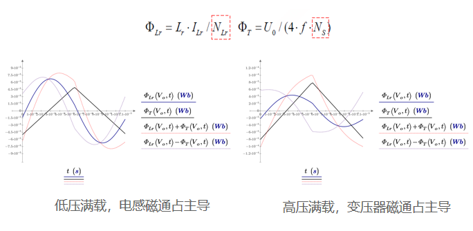
Taking the LLC topology as an example, the magnetic flux of the inductor is proportional to the resonant current, while the resonant current is negatively correlated with the output voltage, meaning that the higher the output voltage, the smaller the resonant current. For transformers, their magnetic flux is proportional to the secondary voltage, so the higher the output voltage, the higher the magnetic flux of the transformer.
This leads to two extreme situations: when the output voltage is at its lowest and fully loaded, the magnetic flux of the inductor dominates; When the input voltage is at its highest and fully loaded, the magnetic flux of the transformer dominates. This means that under different operating conditions, the peak value of the superimposed magnetic flux may appear in any operating condition, and is related to the turns ratio of the transformer and inductor.
The fifth is to combine circuit simulation tools to design the number of turns for transformers and inductors.
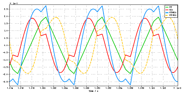
In the design process, once the magnetic core is selected, the main task is to design the number of turns for the transformer and inductor. To avoid tedious formula derivation, it is recommended to use circuit simulation methods. Through circuit simulation, it is easy to obtain the excitation current and resonant current. Based on the excitation current, excitation inductance, resonant current, and resonant inductance, the magnetic flux of the transformer and inductance can be calculated, and the magnetic flux (magnetic flux divided by the number of turns) can be obtained.
By using the number of turns of transformers and inductors as variables, it is possible to analyze the amplitude changes of superimposed magnetic flux under any operating conditions. For non-public yoke parts, as their amplitude is usually small, there is no need to pay special attention. Through circuit simulation, it can be ensured that the magnetic flux density value is less than the set value under any operating conditions.
The common yoke is not only used for magnetic integration, but can also serve as a common edge pillar. The specific plan includes two types: single-sided common edge columns and double-sided common edge columns. In addition, besides forward and reverse stacking, orthogonal stacking can also be used. For example, by performing a 90 degree vector orthogonality between one magnetic flux in the vertical direction and another in the horizontal direction, the amplitude of the magnetic flux can be reduced.
From the perspective of circuit topology, in order to improve the common mode circuit of LLC topology, sometimes the inductance is actively split into two and integrated on both sides of the upper and lower yokes of the transformer. Similarly, the resonant inductors on the primary and secondary sides of the CLLLC topology can also be integrated separately on both sides of the transformer to optimize the overall design.
Through the above design strategies and optimization schemes, it is possible to effectively reduce magnetic flux density, improve system efficiency, and solve local temperature rise problems in magnetic integration design.